Tuesday, May 8, 2012

How-To: Make 37 Degree AN Hard Lines

Story and Photos by Matthew Eddy


OEM brake tubing in the US have what is called a 45° double flare at the ends which means the end of the tubing is folded in on itself and flare at 45°.  A flare nut then crushes the tube end against the mating surface to make seal.  After the flare has been crushed it will require more torque to seal seal each time the system is disassembled and reassembled as well as the potential for fatigue cracks to form where the metal has been folded over.  This is fine for the commuter-consumer they aren’t going to be swapping out components from week to week or season to season.  Racers tend to tinker with their cars and may have to dismantle everything or replace components frequently so they need components that are designed to be disassembled and reassembled multiple times.  The 37° AN flare is a single flare is backed up by a tube sleeve that is held to the mating part with a nut and is capable of being disassembled multiple times without fatiguing and since it’s a single flare its actually easier to make than a double flare.  Additionally this method is rated at higher pressures and is held to a higher standard so the system is more robust and can endure the extremes of racing.  It is fairly common for a race team to immediately replace all stock brake lines with the 37° AN flared tubing as part of prepping the car for racing.
The down side of the AN flare is that the components are much more expensive and they also require an adapter to connect them to the stock brake components such as the master cylinder, proportioning valves and ABS block.  Also the tools tend to be more expensive but you can find a 37° flare tool on Summitracing.com for about $30 HERE.   If you decide to upgrade your brakes to the AN fittings then you can save yourself some money and time by only replacing the lines that run from the ABS block  (or the proportioning valves for those cars without ABS) to the calipers and leave any plumbing that might be going from the master cylinder to portioning valves or ABS block. The AN fittings can also be used for routing fuel, vacuum lines, and various other fluids.  Make sure to use STEEL fittings on the brakes or any other high pressure hydraulic systems and you can use aluminum fittings for anything else.

It is pretty easy to convert to AN flared lines but there are a few more parts you need to buy.  I would suggest getting stainless tubing and an appropriate tubing cutter because the $5 Acme Autoparts special will just cry when you try and cut a stainless line with them; they are barely adequate to cut a regular steel line.  Try this one from Mcmaster-Carr: part number 2764A14.  I haven't use this particular one but it does say its for stainless and titanium.

Step 1:  Cut the stainless tubing to length and deburr the ends.  PUT THE HARDWARE ON THE TUBE!  Easy to forget this step you get so excited about flaring the brake line and forget to put the hardware on.  So put on a TUBE NUT, then a TUBE SLEEVE.  Make sure they are facing the right direction.  See pictures at bottom. 

3/16" Stainless Brake Line Cut and Deburred.


Step 2: Clamp the tube into the flaring tool.  It should be sticking a little above the surface of the tool.  The one pictured below is from Summit Racing.  You can find it HERE.

Summit Racing 37 Degree Flaring Tool


Make sure you clamp this down TIGHT.  If its not tight enough the tube will just slide out.  I used a wrench as shown below to get it extra tight.


Use a Wrench to Tighten Flaring Tool.

Step 3: Flare it!


Summit Racing 37 Degree Flaring Tool in Action.

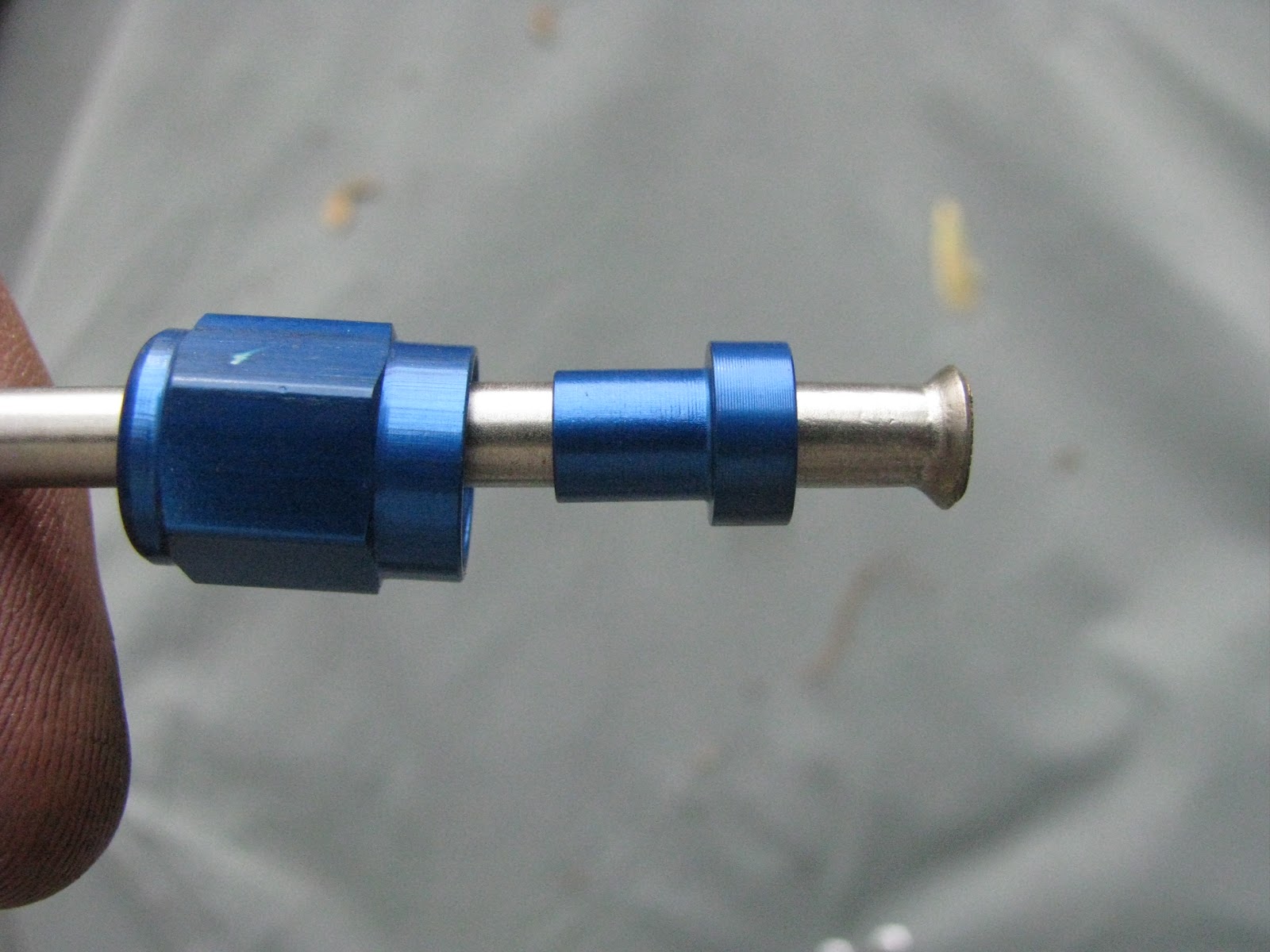
Successful 37 Degree Flare
Here is a picture with all the hardware on behind the flare.  These are aluminum fittings, so this isn't to be used for brakes.  The steel ones usually are plain zinc. Left to right are the tubing nut with the threads on the right side followed by the tube sleeve.  The sleeve will be beveled on the side that will sit behind the flare. 


37 Degree -3AN Fittings on Stainless 3/16" Tubing.

37 Degree -3AN Fittings on Stainless 3/16" Tubing.

37 Degree -3AN Fittings on Stainless 3/16" Tubing


The adapters you will need to connect these to the master cylinder for instance look like this.  Most domestic car makers use 3/8-24 (I think) so need this adapter HERE.  Japanese tend to use M10x1.0 so you use this adapter HERE.  These adapters simply screw into the MC or proportioning valve then the new AN fittings screw to these.

Tuesday, May 1, 2012

Baffled Oil Pans Explained

Story and Photos by Matthew Eddy

Outside View of Baffled Oil Pan for 5.0L Mustang


Normal production cars have what is called a “wet sump” meaning the majority of the oil is stored within the oil pan.  A pick up for the oil pump is located in the oil pan and sucks the oil up to lubricate critical areas within the engine.  This system is used because it is simple and cheap to manufacture and is more than sufficient to meet the needs of the commuter consumer.  However, in motorsports the car and engine are going to be subjected to high g-forces for an extended period of time which the wet sump system may not be able to cope with.  For example, in a long continuous high g turn, the oil will slosh to one side of the pan away from the oil pick up.  No oil gets sucked up and starves the engine which leads to excessive wear and catastrophic engine failure in a pretty short period of time. 

The best method to prevent oil starvation is to go with a dry sump system.  This is used in pretty much all the top racing series cars such as Formual 1, NASCAR, Indy, and American Le Mans.  There is an oil pan but it has a very limited capacity and the sump pump basically sucks all the oil out as fast as possible and stores it in a oil reservoir the is external to the engine. Oil pressure is maintained by feeding the oil from this external oil tank back into the engine so the engine is never wanting for oil.  An added benefit of this system is since the oil pan is very low profile, the engine can be lowered to lower the cars center of gravity.  Unfortunately these systems are very expensive.  A bargain basement pump will run you at least $800 and could run upwards of $2000.  Not to mention a new, possibly custom, oil pan, lines, oil reservoir and more. 

Most weekend warriors can’t justify a dry sump system especially if you are just a track day junkie who doesn’t really have a prepped car but there are a couple lower cost alternatives.  One is to get or make a baffled oil pan.  This will limit how much the oil able to slosh around and hopefully keep it where the pump can suck it up into the engine.  Simply put a baffled oil pan will has chambers that make it easy for the oil to travel toward the oil pick up but difficult for it to get sloshed the other way. Also, they tend to increase the capacity of the oil pan so that more oil will be available in the whole system. 

Below you can see a picture of a Ford Racing baffled oil pan out of a 5.0L Mustang.  This one is used mainly for drag racing but the concepts are the same between drag and road track with some design differences to account for lateral acceleration (g-forces experienced while cornering).  

Baffled Oil Pan from a 5.0L Mustang

You will notice the oil pan has two compartments, a shallow on the right side of the picture and a deeper one on the left.  The reason for the compartment on the right (which is the front of the engine) is to allow space for the oil pump.  The hump that separates the two compartments is required to clear the front cross member that goes under the engine.  In the left compartment is a square chamber that that is designed to trap oil and that is where the oil pick up is located.  At first you may be wondering why is seems to be cordoned off, but what is difficult to see in the picture above are the trap doors that only open inward to allow oil to enter the chamber but not exit (see picture below).  A few other features to note are the lips at the top of the chamber and also one on the left side of the center hump.  These lips prevent the oil from splashing up and out of the camber.  The pan is designed such that for the oil to travel from the left or right side of the pan (up and down in the picture), it must pass through the oil pick up chamber where it will be trapped.  


Baffles in Oil Pan
Above you can see a close up of the baffling in the oil pick up chamber.  The doors can only open inward which will allow the oil to enter but not exit.


Oil Scraper in Mustang Oil Pan
The feature pictured above is called a scraper.  As the crank spins, beads of oil are flung around the inside the engine.  The scraper catches most of these to prevent the oil from going up into the cylinders and instead returns it to the pan.  


In the near future I plan to make one of these for my V6 MR2 and when I do so, I will be posting a "How-To" article.